NRES Instrument Architecture
A full NRES installation accepts light from two 1-meter telescopes, each with an Acquisition and Guiding Unit (AGU) at the focus. Each AGU couples starlight from the telescope into a "star" optical fiber, which transports it to the spectrograph. Both star fibers are connected to the spectrograph at all times, so either telescope can be used to feed the spectrograph. Each AGU also contains (1) a CCD camera to acquire the desired target star and keep its image on the star fiber, and (2) internal switching optics that can couple calibration light into the star fiber, and allow special daytime transmission calibrations.

Above: A top view of an NRES AGU before it's installed.
About 15 meters from the telescope domes is a temperature-controlled room (the "Igloo"), which holds the bulk of the spectrograph systems: the Calibration System, several layers of temperature control, a constant-pressure vessel, the Exposure Meter, and the Spectrograph itself.
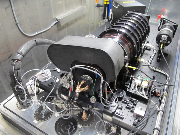
Above: An NRES unit before the thermal shield in an Igloo, before being covered by the semi-cylindrical constant-pressure vessel.
The spectrograph is always coupled to the (one or) two star fibers, and also to a single "reference" fiber. Light from these 3 fibers appears in the spectrograph image plane as 3 parallel cross-dispersed echelle spectra, with the spectra from different fibers separated from each other by about 20 pixels (300µm) in the image plane. The reference fiber always carries light from the Calibration System straight to the spectrograph. Each of the two star fibers may carry starlight, or it may carry reference light which originates in the Calibration System, passes through optical fibers out to the AGUs, and then is coupled into the corresponding star fiber in place of light from the telescope.
In a 1-telescope system, one of the three star fibers is never illuminated.
The Calibration System is an optical beam switcher that allows light from any of three sources to be coupled to three different outputs. The three sources are a tungsten-halogen (TH) lamp and two ThAr lamps, a "master" and a "slave". One of the three outputs goes to the reference fiber; the other two go to the AGUs, where they may be coupled back to the spectrograph through star fibers. Each Calibration System output has an independent shutter, so the three outputs may be passed or blocked in any combination. The reference fiber output has an adjustable neutral-density filter, so that the intensity of its output may be reduced by up to a factor of 100, to prevent overexposure of the ThAr reference lines during long stellar integrations.
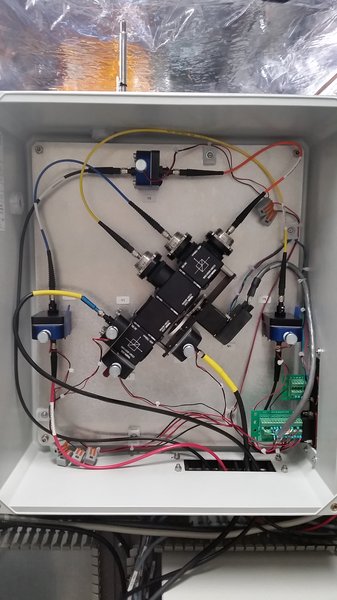
Above: a top view of the Calibration System.
Light passes through several thermal control layers and the constant-pressure vessel wall via a trifurcated optical fiber bundle. It is admitted to the spectrograph proper through the main shutter, which blocks or passes the light from all 3 fibers together.
Light reflected from the AR-coated first surface of the cross-dispersing prism is reflected back into the Exposure Meter. This unit re-images the three spectrograph input fibers onto another trifurcated fiber bundle, which carries the light out of the pressure vessel, where the fiber tips are imaged onto a CCD camera. In this way, the Exposure Meter provides a continuous record of the light intensity emerging from each of the 3 input fibers.
The spectrograph's main CCD detector is a 4K x 4K Fairchild chip with 15µm square pixels. The CCD is cooled to -90C with a cryotiger. Dedicated thermal servos hold the coolant lines and the cryostat housing at the same temperature as the pressure vessel interior.
The main CCD controller, the thermal and pressure control electronics, the cryotiger, and the Calibration System all reside inside the 2nd thermal control layer (the Igloo wall is the 1st), where the temperature is stable to about 0.1 C RMS.
A complete NRES installation therefore involves 2 telescopes, 4 CCD cameras, 3 light sources, and a collection of shutters, drive motors, and temperature-, pressure-, and position-sensors. This complexity is reflected in the reduction pipeline and the resulting data products.